Operational baseline / re-baselining
CFM56-7B24
The CFM56-based model is the working baseline used to develop TurboFanModel, TurboFanLab, the component-map workflow, spool dynamics, controls, and dynamic FlightGear integration. It is now being re-baselined with the same public-data and traceability methodology being used for the GE90-115B.
Model status
Working model, formal audit next
The present engine is operational and has accumulated both static and flight-test experience. Its major design anchors were selected to represent a CFM56-class engine, and the model uses generic OpenMDAO pyCycle HBTF/NPSS map surfaces for Fan, LPC, HPC, HPT, and LPT behavior.
The current map files are not proprietary CFM56 component maps. The re-baselining effort will establish a CFM56-7B24 master parameter set from public sources, classify every important value as published, calculated, estimated, or tuned, then re-scale and validate the map set against those targets.
Current model definition
Selected baseline anchors
These are current TurboFanModel configuration values, not a claim that every value is direct manufacturer data. The re-baselining work will attach a provenance classification and source to each value.
| Parameter | Current value | Current role |
|---|---|---|
| N1 100% design speed | 5,200 rpm | LP-spool speed reference |
| N2 100% design speed | 14,500 rpm | HP-spool speed reference |
| Design core mass flow | 58 kg/s | Map/engine size scaling anchor |
| Bypass ratio | 5.1 | Bypass-to-core flow design anchor |
| Fan design pressure ratio | 1.55 | Fan-map scaling anchor |
| LPC design pressure ratio | 1.75 | Booster/LPC-map scaling anchor |
| HPC design pressure ratio | 11.0 | HPC-map scaling anchor |
| Design T4 | 1,550 K | Turbine scaling reference |
| HPT design expansion ratio | 3.8 | HPT scaling anchor |
| LPT design expansion ratio | 3.2 | LPT scaling anchor |
Component maps
Current map basis
The following plots are generated directly from the current TurboModel map files. They show the published OpenMDAO pyCycle HBTF/NPSS source-domain speed lines used by the model. Simulator-grade low-speed extension rows are intentionally omitted from these online plots. These curves are generic aerodynamic map data and should not be interpreted as proprietary CFM56 maps.
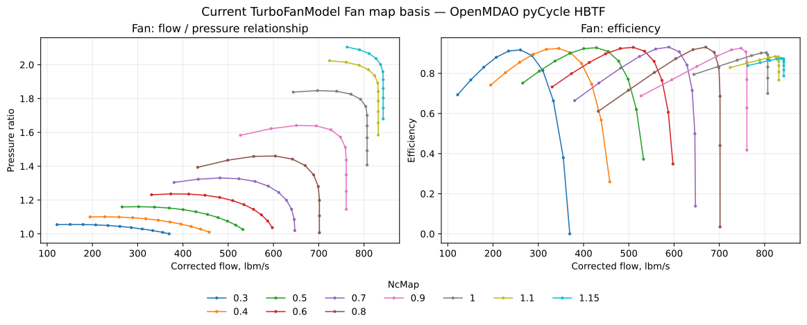
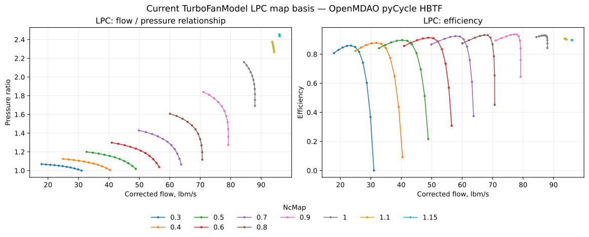
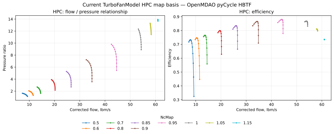
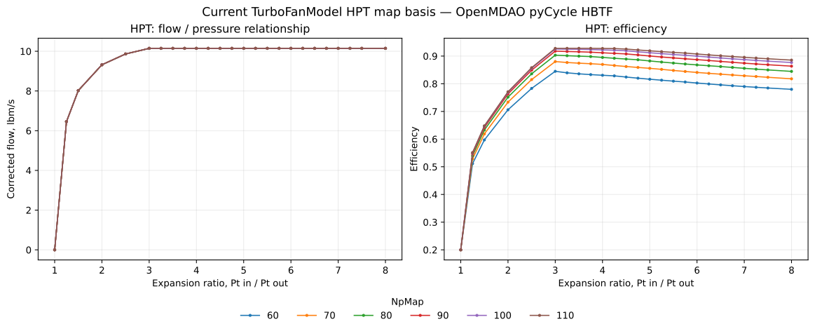
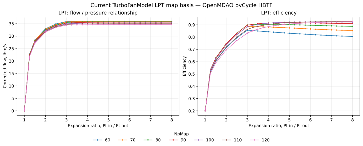
Map provenance recorded in the current TurboModel source: OpenMDAO pyCycle HBTF maps, converted from the published NPSS-format map data. The current source files identify low-speed simulator extensions separately from the published map region.
Engine-specific documentation
CFM56-7B24 Documents
The CFM56 documentation set will be developed as the present working model is re-baselined against public CFM56-7B24 data. Documents will remain with this engine page rather than in the project-wide Documents section.
In preparation
- CFM56-7B24 Modeling Basis
- CFM56-7B24 Master Parameter Set
- CFM56-7B24 Component Map Set
- CFM56-7B24 Validation Report
Dynamic validation
From the Lab to the aircraft
TurboFanModel can be dynamically coupled to a flight simulation that provides data of flight performance for calculating engine performance, placing the engine model into a continuously changing flight environment and creating a genuine closed-loop simulation.
Next CFM56 work
Re-baselining sequence
- Build a CFM56-7B24 master parameter table from public certification, manufacturer, NASA, and research sources.
- Classify each engine-defining value as published, calculated, estimated, or tuned.
- Reconcile the Fan/LPC/HPC pressure-ratio split, efficiencies, corrected flows, turbine work, cooling/bleed assumptions, and spool inertias.
- Re-scale the generic pyCycle maps to the revised design targets.
- Repeat TurboFanLab steady-state and transient tests.
- Repeat closed-loop FlightGear tests and freeze a documented CFM56-7B24 baseline.